Saturday, 4 September 2021

Describe DWDM development of multiple wavelength with the help of a neat diagram. State its advantages also

Describe DWDM development of multiple wavelength with the help of a neat diagram. State its advantages also

Fig shows DWDM deployment on an OC-192 trunk ring for wavelength.

DWDM is a technology that puts together multiplexes data signals from different sources so, they can share a single optical fiber pair while maintaining complete partition of the data stream.


Individual signal is carried on a separate light wavelength. The dense part of DWDM refers to the fact that more than 80 separate wavelength, each about 0.8 of a nano-meter (nm) wide can short a single optical fiber.


DWDM allows enormous amount of data to traverse a single network link. Because they are

carried an clear wavelength, the streams also called channel do not interfere with each other.

Consequently data integrity if maintained of well as any security related positioning is also maintained.


Advantage:-

i) Improve scalability

ii) Provide extra resilience

iii) Maximum Capacity system available.

iv) Greater fiber capacity

v) Easier network expansion

vi) Can conserve switched bandwidth

vii) DWDM System Capable of longer span length

True or False in maths

1)  If A = {1,2,3} then {2,3} is proper subset of A.

True

False

Ans:- True


2) If A = {1, 2}, B = { 2, 3, 5 } and C = { 1, 2, 5 } then find A intersection B intersection C.

{2}

{1}

{3}

Ans:- {2}


Friday, 3 September 2021

What is the difference between potentiometer as an error detector and synchro as an error detector

 1) Potentiometer →  Two pots connected in uniform.

2) Synchro → Interconnection of a synchro transmitter and synchro control transformer.

3) Potentiometer → Potentiometer as an error detector associated with angular as well as linear position control system.

4) Synchro → Synchro as an error detector associated with only angular position control.

Enlist the effect of adding a zero and a pole in transfer function of system

 When a zero is added in the transfer function

1) Bandwidth increases, hence rise time decreases

2) Setting time increases

3) System more stable


When a pole is added in the transfer function

1) Bandwidth decreases hence rise time increases

2) Resonance peaks (Mr) increase

3) System become less stable

Friday, 13 August 2021

Draw the diagram of two fiber UPSR and explain how it is useful in stand by mode of continuous fiber optic communication


Draw the diagram of two fiber UPSR and explain how it is useful in stand by mode of continuous fiber optic communication
Block Diagram of Two fiber UPSR


The full form of UPSR is Two Fiber Unidirectional Path Switched Ring (UPSR).
Normally the working of traffic travels clockwise around the ring on primary path.


Connection from Node 1 to Node 3 links 1 & 2.
Traffic clockwise path is the protection path, if the link or Node fails, protection path (Link 5 to 8) is indicated by dashed lines.


To achieve protection, signals from a transmitting Node is a dual fed into both primary and protection fiber.


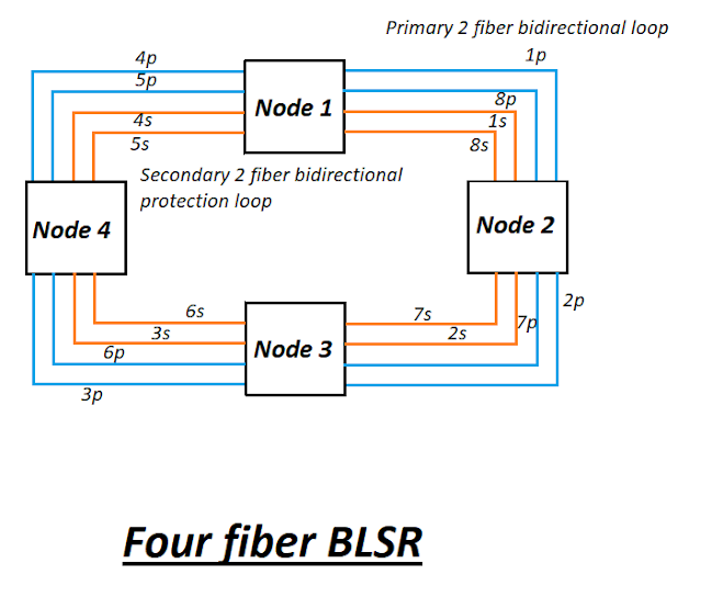
In case of failure of fiber optic communication, how does four fiber BLSR help. Explain with neat diagram


In case of failure of fiber optic communication, how does four fiber BLSR help. Explain with neat diagram


The full form of BLSR is Bidirectional Line Switched Ring.
Two primary fiber loops (1p to 8p) are used for normal bidirectional communication.
And other two secondary fiber loops are stand by links for protection purposes (1s to 8s).


Lets consider, the connection between Node 1 and Node 3 then traffic from Node 1 to Node 3 flow in clockwise direction links 1p & 2p.
In return path, traffic flow counter clockwise from Node 3 to Node 1 along links 7p & 8p.
If a transmitter or receiver circuit card fails, then the affected Node detects a loss of signal condition.
And switches both primary fiber connecting Nodes to secondary protection pair.

So in that condition four fiber bidirectional line switched ring is very useful and helpful.


Thursday, 12 August 2021

Explain the operation of line interactive UPS with the help of neat block diagram

Explain the operation of line interactive UPS with the help of neat block diagram
Line Interactive UPS


 Operation Mode 1:-  When mains is ON, static switch is closed.

                                                  Load get connected directly to the AC mains through inductance (L).


                                        Inverter cum charger blocks operates as charger a battery bank.


Operation Mode 2:- When mains is OFF (fails) static switch is open.


                       Inverter cum charger and battery supplies power to load through inverter.                                                            


The sum of 5 by 14 and 4 by 8​

 Solution:- 

The sum of 5 by 14 and 4 by 8​

(23.8 – 2.49) x (4 x0.15)

 Question :- (23.8 – 2.49) x (4 x0.15)

         =  (21.31) x (0.6)

         =   (12.786)  Ans.

Popular Posts